Materials required:
- Game.com game catridge
- Phillips head screwdriver
- 2 position switch (I used this, but any will do)
- EEPROM programmer (I used the “MiniPro” TL866CS)
- Materials to connect the cartridge, switch, and programmer (up to you, but specific recommendations given below)
Instructions:
Tiger Game.com cartridges can be dumped through any EEPROM programmer that can read from 27C080 integrated circuits.
The main hurdle to dumping the cartridge therefore is to get the pins on the cartridge to map to the correct positions for the 27C080 integrated circuit. Additionally, while many Game.com games will fit well within the 27C080’s maximum size of 1 megabyte, some will require the addition of a two position switch to the pinout remapping so that two dumps can be done; one of the lower half of the ROM, and then another of the upper half of the ROM. The two halves can then be joined together using any file-joining utility.
To determine if your cartridge requires two dumps, use a phillips head screw driver to open the plastic shell of the game cartridge, remove the circuit board, and check the ID markings on the board to compare against this list:
71-516CD-3  256-Kbit
71-529-1      2-Mbit
71-525-1      8-Mbit
71-728-1      8-Mbit (Transistor)
71-709-1     16-Mbit (Transistor)
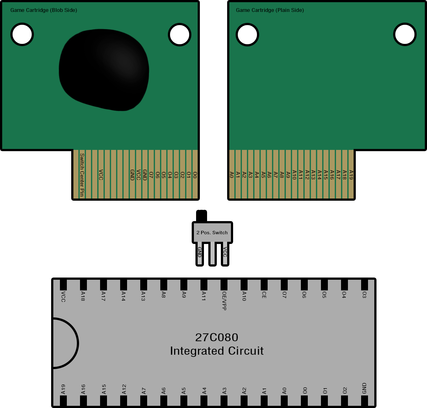
The mapping of the game cartridge’s pinout to the 27C080 IC (as well as the 2 position switch) can be found in this diagram:
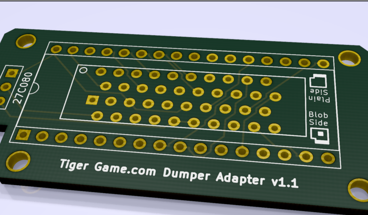
Any method of making the correct connections between the cartridge’s pins, the switch, and the EEPROM reader in a safe and stable manner is acceptable, although my recommended method would be to create an adapter using a custom printed circuit board (PCB) that has traces making the required connections, as this will provide a sturdy, reliable, and reusable adapter.
Materials Required for PCB Approach:
- 2 position switch (I used this)
- Catridge edge connector with 40 positions (I used Sullins RBB20DHHN)
- Strip of 32 breakaway header pins, broken into two strips of 16 (I used Sullins PREC032SAAN-RC)
- Custom PCB with connections for the components listed above (I used this PCB project file)
- Solder + soldering tools
Instructions for PCB Approach:
A printed circuit board can be created in a PCB design program (such as KiCAD, which is free), designed such that pads and connective traces are laid out that will connect the cartridge edge connector, the two position switch, and the two rows of header pins to the specifications of the pinout mapping diagram seen above. This part is a little complicated if you’ve never used one of these programs before, but it’s definitely manageable, and there are many guides out there to assist you. If you find connecting all the pads with traces daunting as I did, Google “KiCAD autotracer” for a tool that can automate the process. Alternatively, feel free to simply use the KiCAD project file I’ve linked to above.
Once you have your PCB file, you can then have it manufactured by one of the various PCB services out there (I had mine made on the cheap with about two weeks between order and delivery at OSHPark.com).
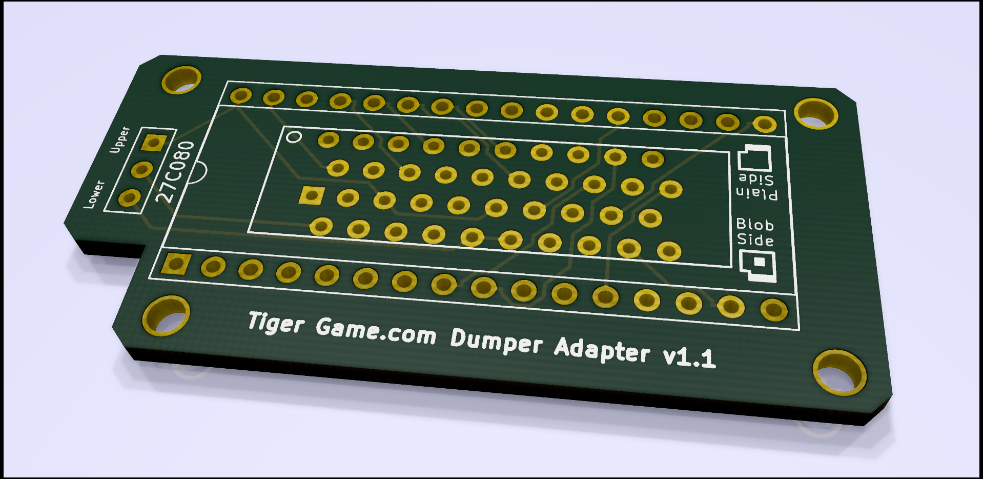
With your board now in hand, the only task left is to solder all of the components to the board. Make sure you solder the edge connector down in the correct orientation (there’s a little circular hole in the top left corner).
Instructions for Dumping the ROM
Once you’ve completed whatever method you chose to make the connections and built an adapter for the 27C080 integrated circuit, all that is left is to mount your adapter onto your EEPROM programmer and read the data off using the 27C080 setting.
First ensure that you have your adapter oriented to correctly match the sockets in your EEPROM programmer. Even though the connections coming out from the adapter could fit into the programmer in two orientations, only one is correct. There should be a half circle mark on the programmer, similar to the one in the pinout diagram above, and your connections corresponding to VCC and A19 should be closest to the side of the programmer with that mark.
If using a cartridge edge connector like that from the PCB instructions, insert the game cartridge’s circuit board into it with the side that has the blob on it facing away from the circular notch in the top left corner of the cartridge edge connector.
When dumping your game, confirm that the 2 position switch is in the “lower” position (the GND position) for the dump, and then, if necessary, switch it to the “upper” setting (the VCC position) for the second dump (see the table of ROM sizes above to determine if two dumps are necessary for your game cartridge).
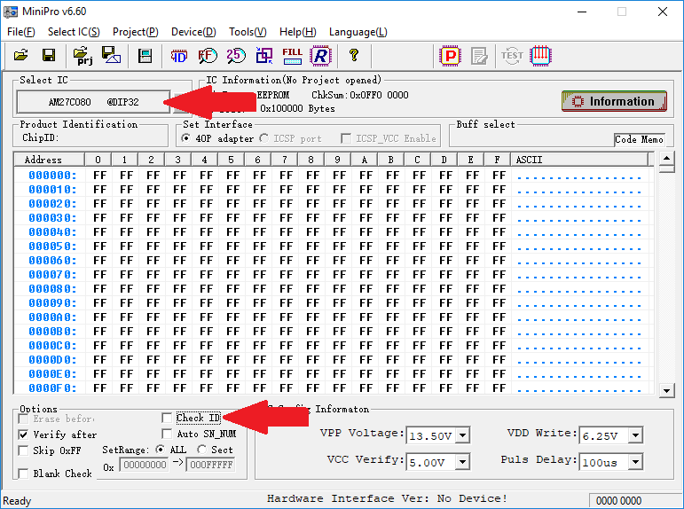
If you’re using the MiniPro software that comes with the TL866CS EEPROM programmer, you’ll want to uncheck the “Check ID” option as well as set the IC Device to any of the 27C080 @DIP32 device options available (I used AMD’s AM27C080 @DIP32).
If your ROM required two dumps you can now join the two halves together with any file joining utility. Windows has one built in that can be accessed via run->cmd, going to the directory where your two ROM dump .bin files are, and typing the following command:
copy /B *.bin output.bin
Make sure that the .bin file representing the “lower” half of the ROM is named something that puts it alphabetically before the “upper” half.
e.g. “myRom_Lower.bin” and “myRom_Upper.bin”
And that’s all there is to dumping Tiger Game.com games!
A huge, huge thanks goes out to parasyte, who was the one who figured out how to dump Game.com ROM data, and without whom the information in this guide would not exist. Thank you!
Disclaimer: these instructions are offered for educational purposes only. No guarantee is made regarding their completeness or accuracy. Their author cannot be held liable for any damage to property, injury, etc. that may occur during their use.


Can you provide pictures how the PCB can be adapter to a adruino Mega